Search This Blog

Thursday 27 November 2014

What do I need to build a wooden clock

I shall start this list by saying that building a working wooden clock is not easy, it takes a lot of patience and a certain level of competence in the use of woodworking tools. If you don't have this then it may be best to work on a few less complex projects first so as to build some of the basic skills that you will need.
If you are an Engineer or Woodworker you will be fine, you already know that things will go wrong and you have a basic skill set that will enable you to work out the best solutions.

Having said all of that building a clock and getting it running gives a terrific buzz, so the project is well worth working at.

There will be many people coming to this project with some form of CNC machine in the workshop ready to start cutting wood, and that is a good start, but remember there are a lot of components in the clocks that can't be made on a CNC machine, round component, metal components and all manner of purchased items such as screws and pins. So I am going to start this list from the bottom upwards, there is a certain minimum level of equipment that you need to be able to accurately make the clock parts and then to assemble and problem solve the issues that arise.

First the simple basic stuff, hand tools, the picture below shows what you will need to cover all the work that will need to be done by hand.


Most of the tools shown above are fairly obvious, and you probably have them already. Some of the others less obvious, the drill set with drill 1 to 6 mm in 0.1 increments or the imperial equivalent are needed to drill the holes for the shafts and the clearance holes for fitting pins. The reamers are needed to accurately size the holes for the bearings and shafts, I use  a 4,6,10 mm reamers
Vernier calliper for accurately measuring, and a small ruler for the same. The Danish oil for finishing of the wood to seal the surfaces and the Dry film lubricant to lubricate the gear teeth and moving parts, grease shouldn't be used

Power tools are probably more commonly available than the hand tools above, so the ones I would normally include as being required for clock building are shown below


You could almost say that the above tools are all that is needed to build a clock, the truth is though you really need something to support the drill in a vertical position for accurately drilling holes. You also need a means of clamping the work piece whilst it is being drilled and for preference some means of adjusting the position of the work piece beneath the drill. To do this you need will need one of the arrangements shown below.


The Drill stand will support the drill vertically and provide a handle to feed the drill bit into the work. The vice on a cross slide is the ideal means of clamping the work piece below the drill to give it both support and adjustment, but you can get away with the simple vice arrangement on the left. The arrangement on the right is from Proxxon looks ideal but may be a bit small.

I have shown the coping saw amongst the hand tools and I guess you could attempt to cut all the clock parts with one of those but it is not really practical. The most common way of cutting the parts would be either to use a Scroll Saw or a CNC router


The saw shown is ideal for cutting the gears and all the other flat parts in a clock and many of the clock builders use a saw like this to do just that. There is an alternative to this and that is to use a small bandsaw as I did for my first clocks, but the scroll saw has more control and hence precision in the cutting.

If you are simply interested in building your clock with the above equipment you need read no further as you have chosen the route that will not break the bank but will still give you great satisfaction but probably a lot harder work.

There a quite a few components in the clocks that are round and not suited to either Scroll saw or CNC routing, so you need to either out source those parts or be creative and change the design to use materials you can work with. Sleeves are on example that are ideally made on the lathe but can be made from dowel in shorter lengths and then drilled, or simply substituted with clear plastic tubing. 


The lathe shown above is a small bench top machine ideally suited to the needs of the clock builder.

If you are going spend more on you workshop then the next step up from the drill stand and the cross slide vice, is a small milling machine. This will provide all of the features of the drill stand and cross slide vice but with graduated slides to give you movements with precision. With a simple vice mounted on the table you have all the precision you will need to drill, ream and mill those components that do not lend themselves to CNC machining.


The main alternative to the scroll saw is to use a CNC router or laser, this is a big step up in price to purchase not only the machine but all the software needed to use it.


The software requirement to run a CNC machine is considerable and can be costly if you are to use the mainstream commercial software. 


For a start you need a CAD program to make any changes to the DXF files you feel that you want to make, or you may simply want to regroup the gears and profiles to suit the way you are going to cut them.

The Cam software is used to take the DXF files and generate cutting paths for the tools you are going to use to cut out the profiles. It then generates the code necessary to cut the profiles on the CNC router.

The CNC Controller actually connects to your CNC router and feeds the code to the machine.

I am familiar with the software shown above but there are many more free and commercial alternatives that you should look at before you actually buy anything.

DraftSight is a good choice for free CAD software it will do all the changes and manipulations you want to do on the DXF files. If you want 3D capabilities choose one of the other two 'paid for' solutions.

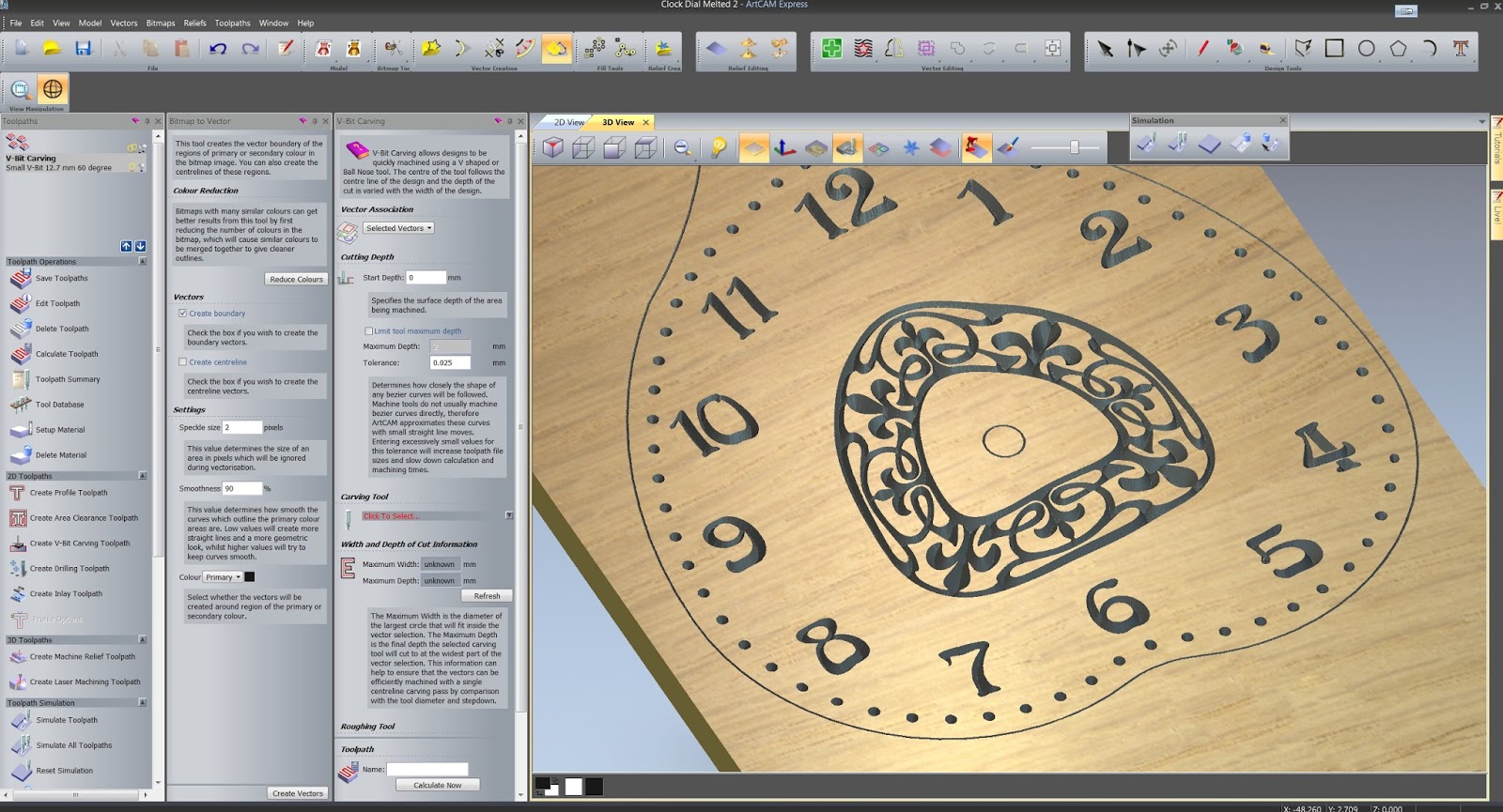
Both Cut2D and Artcam express are simple to use and are relatively inexpensive in this category.

Mach3 is probably the most popular controller, simple to use at a basic level but also with great depth of features if you need them. You will have to pay for this.

I have avoided giving you links to all of these products as you can surf the net as well as I can using the keywords for the items you are interested in. This way you get to choose yourself from the wealth of material out there. However I will make one exception and that is to lead you to this website that has a collection of all the CAD CAM controller software available, mainly free.


Monday 24 November 2014

Clock Dials part 2

Clock designs always need a dial, obviously, so in the past I have always designed the dials within Solidworks as part of the clock design process.


For the next Clock 23 I required something a little different, something in fact quite unusual, so Solidworks was not going to work for what I had in mind. I should explain that Clock 23 is going to be different, all I can say at the moment is that it will use the non round gear set found in clock 18 and an unusual dial, so I shall now explain how I created the dial for clock 23, just the process that is, the actual dial design for the clock may well be different to this.

In the last post on Clock dial construction I explained how ArtCam Express could be used to engrave numerals into the dial surface using V Bit Engraving, it is this technique that I shall use to create the new dial. With ArtCam Express it is possible to convert bitmap artwork into vector form, that can be used  to create tool-paths for cutting on your CNC machine.

The design for the new dial was done in Photoshop, you can use any of the free photo editors listed below to create the dial, I actually started the process in Solidworks to draw the outline for the clock dial so that I knew that the artwork generated at the next stage would fit into the dial shape at the correct size and position. Saving that from Solidworks as a PDF file ensured I could load it at 1:1 scale into Photoshop.


The dial shown above comprises the 12 numerals, the hour and minute indicators and the central floral design. The numerals and indicators were all drawn in Photoshop, but the floral design was a vector downloaded from Craftsmanspace  and loaded into the Photoshop design of the clock face.


The next step was to add some distortion to both numerals and the floral design so as to reflect the distortion of the clock face. This was done using the Liquify tool to manually distort the features. This is now complete so can be saved as a jpeg file for use in ArtCam Express.


The model is loaded into ArtCam using the Open Model command ans after specifying material thickness the dial is brought onto the screen as above.


The next step is to use the Bitmap to Vector Converter to firstly reduce the number of colours down to 2, Black and white. and then to do the vector conversion. Once this is seen to be satisfactory use the V Carving tool to create the toolpaths.


Finally use the simulation tool to create the tool paths and view the rendering of the finished result.


Photoshop Alternatives


Gimp
Paint.net
Pixlr
Picmonkey


Bit Map to Vector Conversion

Wintopo
Autotrace
VectorMagic

Wednesday 12 November 2014

Clock Dials

I have designed and made quite a few Clock dials over the last few years, so I thought it appropriate to record some of the ways in which I have built them.
The dial of course is the face of the clock and although the main interest is usually in all the moving gears behind  the dial does have a big influence over the final appearance.
This list of my build methods is by no means exhaustive, its just those methods that I have tried myself.


This first construction starts with a recessed wooden dial as a base and into that can be inserted either a laser engraved plastic chapter ring or a simpler printed ring.
The latter is the simplest of all the techniques and it is the least expensive, the dial can be printed from a jpeg file created in a paint or drawing program such as Photoshop or one of the many free alternatives. The drawing can be imported from the clocks PDF file and added to or changed as you wish before printing to glossy card.
Laser engraving onto multi layer plastic sheet again using the PDF or DXF files gives you the opportunity to use a thicker material or colours for the dial, but only really realistic if you have a laser machine yourself as it can be expensive if you need to out source it.


This next technique uses individually cut numerals glued directly to the dial face. This method can look very effective as it gives the dial extra visual depth with the shadowing of the letters in different lights. I like this approach myself as it is relatively straight forward if you are creating the numerals with CNC machine, if cutting out by hand it is much harder.


Cutting the the numerals directly into the face provides a nice contrast between a painted surface and the cut surface of the dial. Clock 19 on the left is a good example of where this technique will work well. The numerals are in a bold rounded font so the cutter need for the cut is not too small. The dial on the right is more of a problem because of the fine serifs used in the font, you need to use a very fine cutter to ensure that you can get the fine detail this fonts requires.
To enhance the contrast between the surface and the cut font it is best to paint the surface of the dial before cutting. If you paint first and then coat with a natural Danish oil and then cut, you can use a fine brush to infill the cut with an Acrylic paint. Any over spill can then be cleaned off with a damp rag or even sanded off before finally sealing again with the Danish oil.


To overcome the difficulties with using a small cutter you can instead use a V bit cutter to cut the numerals and the fine marker lines on the dial, some of the detail shown in the dial above would be impossible with a conventional router cutter but with a V bit cutter you can use a technique called V bit Carving which actually cuts the profiles of the numerals in 3D.

The cutter have a V profile finishing in a point so as to get the extreme detail the cutter moves out in the Z axis as it follows the profile so that it is cutting progressively narrower lines.
So the diamond shaped groups shown above come out very crisp and clean but very shallow at the narrowest points.
Again this is best used with a painted surface covered with natural Danish oil and then in-filled with acrylic paint.


The final technique, which I must admit I have not used myself is to inlay a different wood into the surface of the clock face, you start by cutting out the individual numerals and then machine the recess into which the numerals will sit. Glue them in place and the sand flush before finishing. This technique can look fantastic but at the moment beyond my skill set.

A last word on what I use to generate the code to produce the clock faces. In general I use Cut2D for all my general CNC routing, it  works really well cutting 2D profiles for all of the flat components used in the clocks and it is simple to use and understand.. 
What it doesn't do is the V bit carving and for that I use Artcam Express . Artcam can do all of the same things as Cut2D plus V bit carving, what it won't do without an expensive add on is create more than one bridge to hold the component in place, so I use both.
I use Mach 3 to feed the code to the router.


Friday 7 November 2014

How long will my clock run ?

The question is fairly easy to answer, but normally it is asked with the expectation of finding a way to increase the running time.
There are a couple of basic factors that govern the length of time that the clock will run, the first is how far can the weight fall before it hits the ground, as it is shown below the higher you hang the clock on the wall the further the weight has to fall and the longer the clock will run. Obviously there is a limit to high how you can comfortably hang the clock so a reasonable expectation for the weights travel is about 1300 mm. This is assuming that the centre of the dial is set to about 1600 mm. There are some detail consideration that could increase this, first arranging things so that the weight starts off from a higher position and secondly making the weight itself shorter, but 1600 mm is a good starting point.

The second major factor to govern the running time is the diameter of the drum around which the cord supporting the weight is wound, the drawing below is a section through Clock 1 showing the cord wound around the drum, the drum in this instance is Ø 3.8 cm.
For each hour that the clock is running, this drum turns one complete revolution, so the length of cord unwound is Pi x (Diameter^2)/4 = 3.142 x (3.8^2) / 4 = 11.34 cm.
This will give us a total running time of 130.0/11.34 = 11.5 hours.

This is annoyingly shy of 12 hours so lets start looking at how to increase this. I have already mentioned mounting the clock a little higher or optimising the size of the weight itself by making it bit shorter, and perhaps a little fatter. The next simple thing to do is to decrease the diameter of the drum so that it unwinds less cord for each revolution. Although this is easy to do, it has a cost, and that is you will need to increase the weight proportional to the change in diameter. Using the same calculation as before, if we reduce the diameter of the drum to Ø3.2 cm, then the running time will be increased to 16 hours.
There is one other thing that we can do to extend the weights travel and that is to take the cord over a guide pulley as shown below so that the travel can be increased significantly if the guide pulley is fixed much higher up the wall. No increase in weight is involved with this change, but you do have to ensure the clock is is well attached to the wall as the pull of the weight is now going to be upwards instead of down.

The mention of pulley's brings us to the final section that shows how the running time can be increased 2,3 and 4 times by using a pulley arrangement shown below. 
The simple arrangement on the left with the weight hanging directly on the Drum gives us the basic run time. The second arrangement has a pulley added above the weight around which the cord passes to an anchor point on the clock frame. Now as the drum rotates there are two cords supporting the weight so for a given movement of the drum the weight will only move half as far so the running time is doubled.. In the third arrangement 3 cords share the movement, so the running time is tripled , and the final arrangement has 4 cords so the running time is quadrupled
You do however have to remember that the weight has to be increased in proportion the running time gained, so double the running time, double the weight.
You also have to remember that as the weight increase its physical size also increases so any increase in length has to be taken off the running time.


Now finally a drawing showing how a simple 2 fall pulley was incorporated into Clock 22.

For further reading on the subject of Pulley's and weights .


Saturday 1 November 2014

How the Woodenclocks gravity escapement works

When Clock 20 was designed it incorporated the new woodenclocks gravity escapement  The design of this escapement was based on the Arnfield escapement developed by Jim Arnfield in 1987. He devised a method to completely isolate the pendulum from any and all sources friction that could act on the pendulum, something that had never been achieved before. It works by having a separate arm that provides the impulse to the pendulum, its called the Gravity Arm, it provides a precise consistent impulse to the pendulum and isolates the pendulum from any other moving parts in the clock. The benefit of this is that it reduces the sources of error that can creep into the clock mechanism over time. I have modified the design of the Arnfield quite a bit so as to be able to use it in the new wooden clock designs. The escapement release parts have all been gathered together at the bottom of the escape wheel to reduce the inaccuracies that can occur over larger distances when using wood. This also has the advantage of reducing the effort needed to release the mechanism so reducing the over all weight needed to drive the clock. The other major change from the Arnfield design to create a 15 legged escapement instead of the 6 legs used in the Arnfield, this slows down the rotation of the escape wheel so reducing the reduction ratio to drive the minute shaft which in turn reduces the driving weight even more.

The original Woodenclocks Gravity Escapement utilised a 6 legged catch between the trigger and the escape wheel, to arrest the movement, the latest Clock 22 does away with the 6 legged catch and lets the Trigger engage directly, this is simpler and more efficient and is used in the description below.

The escapement components are all shown here in this first view, the Gravity arm has the Lifting lever , the Impulse pin and the Weight mounted on it. The impulse pin is used to transmit the force of the moving Gravity arm into the pendulum, just a small amount to keep the pendulum ticking, this can be adjusted by changing the size of the weight. The pendulum motion is always shown in green arrows in the following, with all other movements and actions shown with red arrows

In this first step the pendulum has reached its left most position and is just turning to swing back to the right, nothing else is moving at this stage.
In the second step the Pendulum has swung over to the right and has just made contact with the Impulse pin. At this time the gravity arm is in its lowest position and it is being held in place by the Lifting lever. The lifting Lever is sitting against one of the curved teeth on on the inner ring of the Escapement wheel and the Escape wheel is locked in place by the Trigger.

In the third step the pendulum starts to push the gravity arm to the right until it reaches the end of its stroke, by which time the the lift lever has dropped clear of the tooth holding it. Its travel is restricted by a stop pin at the top of the lifting lever that holds it in position.

Now its the turn of the Gravity arm to take over and start to push the pendulum via the impulse pin towards the left, over the short distance it travels until it hits the trigger is when it adds the impulse to the pendulum to keep it ticking. The forked end of the lifting arm is travelling towards the curved tooth but it is vital that it doesn't get there before the trigger is released.


When the finger contacts the trigger it pushes on it and it turns and disengages from the the Escape wheel, this in turn will allow the escape wheel to start turning and push the Lifting Lever/Gravity arm back. It should be noted that this release is not felt by the pendulum, so the friction involved in triggering the release is nor felt by it either.


In the final step the pendulum carries on to reach the start point of the sequence and the escapement wheel is once again locked by the trigger returning to its rest position. The triggers centre of gravity ensures it falls back to its stop pin.

Despite the long explanation this is a simple escapement that provides a most accurate method of controlling the motion of the clock.

Finally just 4 points to help setting up the escapement for the first time.

  • The L shaped Lifting lever should be adjusted so that the bottom of the V in the forked end should strike the end of the curved tooth dead on so that there is no slippage as it strikes. The adjustment is made at the top end of the Lifting lever by either adding or removing material from the flat face that contacts the Stop pin.
  • The rest position of the Trigger depends on its small Stop pin so the contact with it should be adjusted so that the actual hook that contacts the tooth on the escapement overlaps that tooth by about 1 mm.
  • The finger on the end of the Gravity arm needs to be adjusted so that it causes the trigger to release the Escapement wheel just before the fork in the fork in the Lifting lever reaches the curved tooth.
  • Finally you could use short lengths of rubber tube to slip over the stop pins to quieten the contact and to also make the above adjustments.