Search This Blog

Tuesday 22 August 2023

Woodenclocks Files - Payment with Credit card

 I use Paypal to pay for the clock plans and files you purchase from me. I use it because it is an easy payment means for the buyer even if you don't have a Paypal account. It is not always obvious how to use it if you want to pay by credit card so I have added an explanation below.


Start by clicking on the payment button highlighted here.


You will need to supply an email address and your name so they know where to send the files once the purchase is complete.


Now click on the text highlighted so you can add your card details.


Finally, add your card and personal details 

 Press the Blue button at the bottom to complete the purchase.

Sunday 28 May 2023

Calibrating your wooden clock


  We all know by now that adjusting your new clock build to tell the right time means moving the weight on the bottom of the Pendulum either up or down to make it run faster or slower. I have always done this manually over a few days, gradually making finer and finer adjustments until a satisfactory accuracy is achieved. I have never achieved better than 20 seconds a day deviation because environmental factors seem to affect the accuracy, so striving for better is usually a waste of effort as it can be changed by the next day.
 The picture on the left shows the back of a new Clock I am working on with the Pendulum weight, in this case, a Brass cylinder supported on a thin disk at the bottom that is a friction fit on the Pendulum rod. The clock rate is adjusted by moving this disk up slightly to make the clock run Faster or down to make it run Slower, the more you move it in either direction the more its rate will change.

Recently, however, I realized that I could use an app on my phone or my iPad to help with this and cut the days down to minutes. These apps use the microphone on the phone or iPad to listen to the clocks ticking and from that calculate the rate at which it is running.


The first of these I used was 'Cuckoo Clock Calibration' on my iPad.In this case, with the new clock, there is a predominant single tic because of the nature of the driving mechanism, so we are looking for BPM of
60 which you can see here is very nearly achieved.


In this second case, I used my Android phone with the 'Clock Tuner' app and again 60 BPM.

In both cases, the apps themselves are capable of much more but we simply need to know the BPM so that we can adjust the rate of the pendulum swing by moving the weight up or down to zero in on the 60 beats per minute. The technique, therefore, is to take a reading, adjust , take another reading until such a time as you can see no improvement.

Friday 28 October 2022

All Woodenclocks Index

 I have an index to all the woodenclocks on the website but it has no images of the clocks only the most salient features being mentioned to aid you in choosing what to look at first. So the following is a list of all the woodenclocks listed visually to make your choice easier.


For more detailed information on each clock then the file below will provide it.


Friday 21 October 2022

Hints and tips for building Woodenclocks.

 Over the years that I have been designing and building woodenclocks, there are some techniques I have developed that either make my work easier or more accurate or both. Some of these I have added to the clock instructions so only get seen if you are building one of those clocks. This article then is an attempt to collect all of these Hints and Tips together in one place.


1) Starting with probably the most obvious one which addresses the problem of gears tending to stick at some point and stopping the clock from running. In the gear train itself one or more of the gears may not be meshing correctly there may be some interference between some of the gear teeth. You need to test each pair of gears in turn by mounting each meshing pair in the frames on their own and turning them by hand very slowly with little pressure. If any pair stick or interfere with the other you should mark the teeth that are affected and carry on until you have turned the large gear around completely then strip down and dress the teeth you have marked until they work together smoothly. Repeat this process so all the meshing pairs of gears are running freely.

It is not sufficient to test them when the gears are mounted in the clock and then left to run continuously with the weight in place as the free-running gears will easily override any slight interference whereas when the gears are running in the clock with the escapement in place they never run fast and so easily feel the effects of interference.


2) Concerning bearing Lubrication the type and viscosity of the lubrication in the “as shipped” bearing is highly significant and represents a considerable drag inside the bearing. I recommend that the grease or oil be soaked out with white spirit, I expect that the solvent leaves a thin residue of lubricant, but it would be wise to apply a little light Machine oil, like that used for Sewing machines or Clippers. The Bearing shown here is of the type termed Needle Roller Drawn Cup.


3) The DXF files supplied with each clock include all the parts that can be cut using the CNC router, they do not include those round items such as the turned parts cut from Doweling nor any pins or nuts and bolts, information on these parts is included in the Detail drawings supplied in PDF format. The parts themselves are laid out in single DXF files ready for you to extract and use in your CAM software. The profiles are shown on 6 separate layers, these being ‘Outside Cuts’ ‘Inside Cuts’ ‘Pockets’ and ‘Non-Cutting Profiles’  'V Cuts' and 'Black' The layers are colour coordinated as shown.  


4) Sometimes it is necessary to make the Pendulum Rod longer than the 700 mm or 1000 mm you were able to purchase. If this is the case you will need to cut down the second piece of tube to the additional length that you require. Now you need to make sure the cut ends are square so that when they are butted together there is no gap. A short length of steel pin Ø 4 mm is used to fit into the ends of the two pieces of tube to support and align them before glueing into place using a strong adhesive like Gorilla glue or Araldite, whilst the glue is setting hold the two tubes along their length to ensure they stay in line. Clean off the excess and wait for a couple of hours until it is dry before you use the new tube.


5) Recommended Ball bearing type is stainless steel with metal shields as these do not actually touch on the balls inside whereas the flexible seals can do. 
A typical designation would be:-
SMR84ZZ Ball Bearing - Ø4 x Ø8 x 3 mm
Or for a flanged version
SMF84ZZ Ball Bearing - Ø4 x Ø8 x 3 mm


6) I always use a Bow Line Knot on the end of the cord holding the driving weight of a clock, it is one of the most useful knots you can know. The Bowline forms a secure loop that will not jam and is easy to tie and untie. The Bowline is most commonly used for forming a fixed loop, large or small at the end of a line. Tried and tested over centuries, this knot is reliable, strong and stable. Even after severe tension is applied it is easy to untie.


7) Hand-finishing all the parts that you have cut can be a tedious process and can be difficult to achieve a consistent finish, especially in tight internal or external corners. To get over this I use Brass piloted router bits to do the bulk of the work, unlike the more usual large Ø12 mm bearing, these use a smaller Brass sleeve as a follower enabling you to get into much tighter places. I find it most useful when using plywood as well as improving the appearance it stops splintering of the top layer of ply or removing any evidence of already splintered.


8) I usually finish my clocks with a coat of Danish oil mixed 50/50 with white Spirit, the second coat at full strength, the second coat I try to stay clear of the faces of the teeth as the coating can take a day or two to dry out and remains a little soft until it is fully dry. I know that some builders like to apply a coat of very low viscosity super glue to the surface of the gear teeth, to give a very hard surface to the tooth surface before the final sanding and this certainly offers the opportunity to get a smooth hard-wearing finish. 


9) I like to make the Back Frame and the Frame Spacers as stiff as possible to avoid the clock distorting under the load applied by the driving weight. To ensure this I always fit the biggest Braces I can between Back Frame and the Frame Spacers and ensure everything is glued together. The front frame is held in place on the Frame spacers by two small Wedges. These have been designed to be an overly tight fit to account for variations in material thickness. To get them to fit properly so that they slide in easily to start with and then become tight when fully pushed in you will need to sand material off the back of the Wedges.


10) On some of my clocks, some shafts really need to have a head on the end to hold in place parts such as gears or ratchet and pawls. If making headed pins is not possible then other solutions have to be used. The pictures on the left show some of the parts that can be used. The best, because it has a head and an accurate shaft diameter is the clevis pin, which can be cut to length and used directly. Simile a round head Nail could be used but the shaft itself is not as smooth or accurate. A small Rod magnet with a diameter larger than the shaft can be simply stuck to the end of the shaft, as long as the shaft is not stainless steel. Last a small plastic washer with a hole slightly smaller than the shaft diameter and a slit through the side to allow it to flex, can be slipped onto the end of the shaft to form a head.


11) When cutting the profiles for parts that are to be fitted together then you are going to need to modify your profile cuts to overcome the problem of fitting square-cornered tabs into the round-cornered holes produced when the holes or slots are cut with a round router bit.

You can do this by modifying the fillet in the manner shown in the sketches to the left here, the holes use a ‘Dog Bone‘ type which has the fillet formed at a diagonal to the corner where the original square corner is cleared out by the fillet whose circular edge just clears the corner. On the external cuts, the fillet is formed with its radius centre on the original cut line, it can be done in either direction as shown in these examples but for preference, I would use the upper example as it doesn't weaken the tab.


12) In some of the simpler clocks no bearings used so the shafts run on the bare wood of the drilled hole. I had noticed when making Clock 21 that using a laser to cut out all the profiles and holes left a burnt surface on all the parts cut this way. This, of course, was carbon which just like Graphite is a lubricant, so as this simple clock design does not use actual bearings, I have attempted to simulate the Laser cutting process by Burning the hole surface with a red hot Ø3 mm rod.

The two photos shown here illustrate the process, the Ø3 mm Rod is held in the drill chuck and then heated to red heat with a blow torch, at which point the front frame with the Ø3 mm holes already drilled is placed on the baseboard below the glowing rod and then the rod slowly fed through the hole to burn its surface, and that's it. You now repeat the process for all the holes that will carry a rotating shaft in the front and back Frames.I have tried this on one of the clock prototype and it does seem to have some merit, I haven't tested it over a long period of time nor have I run comparison tests with an assembly with non-burnt holes but the results do seem encouraging so may be worth giving it a try.


13) You can make the weight from whatever you like, ideally, it should complement the aesthetic of the clock and not look bizarre or incongruous. I favour the brass weight but this is not always practicable and can be expensive. I have used a granite block in the past and more recently used a soft drink bottle or Can. To determine what size weight to use to drive the clock, I normally use a two-litre Coke bottle partly, filled with water to start, and add or remove water to get the clock running continuously. You would do this after assembling the clock and making sure everything is running freely and the escapement is set up correctly. Usually, a bit of back and forth here to adjust the escapement then adjust the weight. The Hanger adapter plate can be cut from 3 mm thick plastic or Plywood, get the DXF file by clicking on the illustration.


Sunday 25 September 2022

CNC Profile cutting - Climb or Conventional cut.

 You are probably aware of these terms in reference to setting up your CAM program when deciding which is going to be the best direction to follow to get your part's cleanest and most accurate finish.

The main difference between climb and conventional cutting is how the cutter bites into the material.

A conventional cut deflects the bit, causing it to dig in and produce a rougher surface, whilst a climb cut pushes the bit away leaving a smoother finish. Because of this when cutting Hardwoods it is generally believed that the best finish will be achieved using a climb cut for the gear teeth on the gears of the clock.

A simple visual check of any off-cut you have made will quickly tell you whether your set-up is correct, if the off-cut is cleaner than your part you have it the wrong way round.


.

.


I would personally always use the Climb cut for all but the last layer where I swap to a single pass with a Conventional cut. This for me gives the best tool usage and the cleanest and most accurate finish.


It should always be remembered when setting up for cutting that you need to change the direction of cut when you move from cutting an Outside profile to cutting an Inside profile. As the cutter only spins in one direction all the time changing to an inside cut always necessitates the cutting direction is reversed.

The illustration below is taken from the Vetric Cut2D worksheet for one of my clocks. This shows all of the parts for a clock laid out on a single sheet ready for cutting. All outside cuts are shown in Blue and all inside cuts are in green along with other colours and layers for non-cutting items like text.


The boxes down the right-hand side are used to apply the settings for the gcode that is generated to be fed to the router. This is where you set the direction of cut and last layer options to reverse them

There are several videos to watch on this topic that can be viewed from the links below.


Monday 15 August 2022

When clock parts are too long to fit in the work table

The Frames and Dial of any clock can be pretty large and therefore not able to be fitted to the Work Table or Bed in one piece. In these circumstances, you will need to cut the part into two or three pieces to enable them to fit. Simple glueing the parts together may well not be enough to ensure that the part is strong enough to function or indeed be accurate enough for the clock parts to be fitted. The following is a guide to a few of the ways to achieve a positive result.

Using CAD

The primary making method for the clock parts is CNC machining and the approach is to split the large part into several smaller parts using your 3D CAD software. I use Solidworks but any of the Free or Paid for CAD programs will be suitable for this task. 


The first step shown above is to use sketch lines to show where the cut needs to be made. My preference in this is to use sketch boxes the size of the cutting table to establish the position for the cuts and then if necessary attach new planes vertical to the cut lines to guide the cut command that follows.


A simple Butt joint simply will not be good enough to withstand the loads applied to the Frame structure by the Driving weight, so there are several options you can use to reinforce the joint before glueing together. The first method shown above requires you to drill 2 holes into each side of the joint and fit steel pins to strengthen the joint. Great care is needed here to ensure accuracy in aligning the holes to each other, if in doubt use one of the following methods instead. In fact, this method is more appropriate if you are 3D printing the parts as it will be easier to accurately produce the holes.


The second method is to glue together the two parts but add a strengthening strip to the backside to reinforce the joint as shown above. Positioning this may be tricky as it may interfere with the gear train on the inside so it may have to be located externally and therefore visible if it is at the front of the clock.


Finally instead of a simple split line, a Lap joint may be more appropriate, with no extra steel pins required and no problem interfering with internal gears. It is produced using a Z cut across the frame as shown in the first picture above and the larger glue surface provides both the strength and accuracy needed for the joint.


Using a 3D Printer slicer

If you own a 3D printer, and you are going to be producing the parts for your clock on this you will have some other options to choose from. You can still use your CAD program to make the changes and output the STL files from there. 

The alternative is to start with the STL files provided and make your changes in your  Printers slicer program or if that's not possible then one of the later model Slicer programs can provide output suitable to your printer. I have used the Prusa Slicer 2  for this article as it seemed a little easier than some of the alternatives.

To see more details in the screenshots below, click on them. 


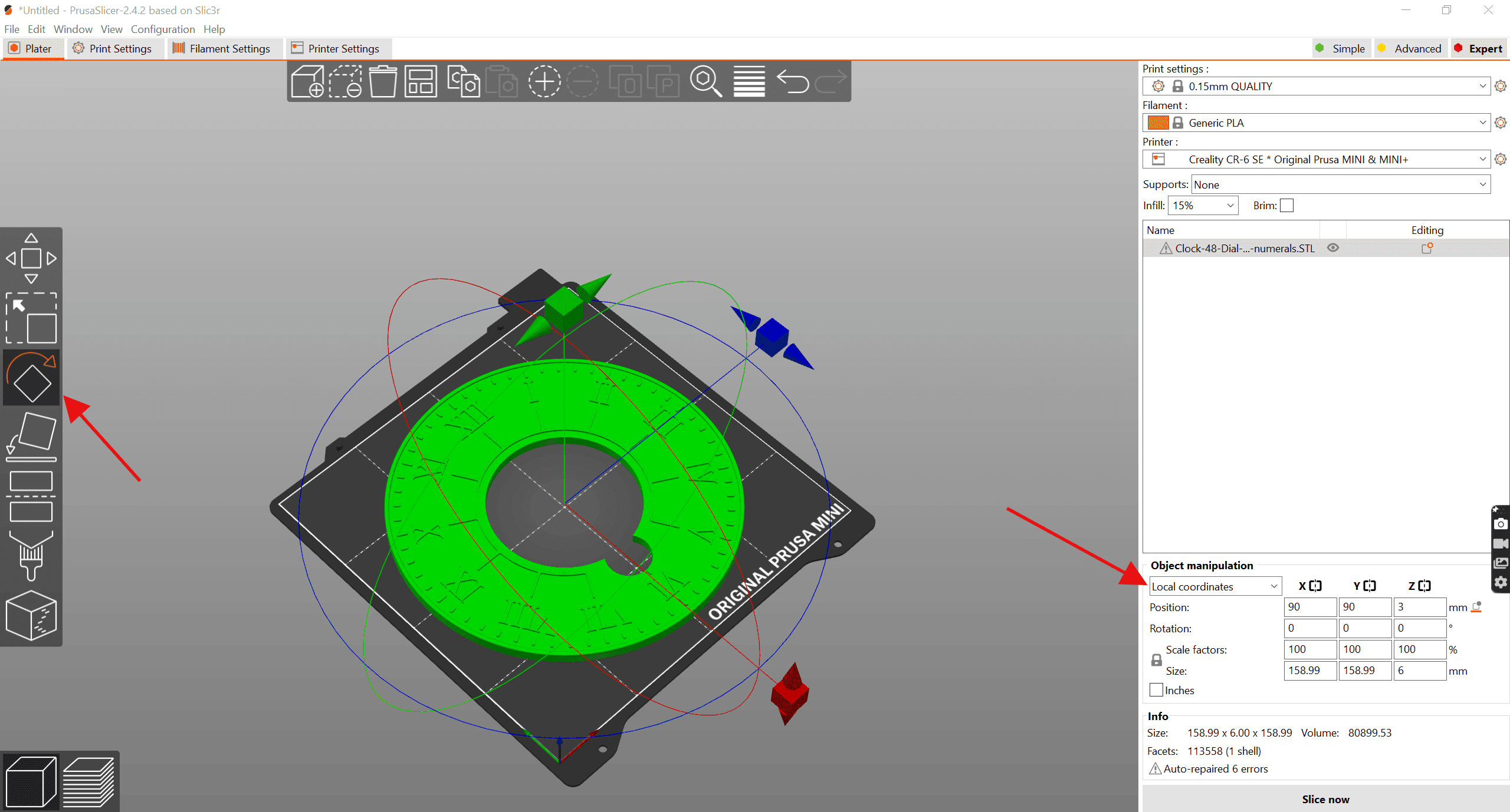
Start by using The File menu at the top left to Import your file to the printer bed, it should adutomatically lay it in the centre as shown here. If it's not green then click on it. You can start making changes to the set-up now, you can change the material you're going to use and change the actual printer you are using. The changes to the position of the part on the bed can be made in the boxes highlighted at the bottom RH corner.


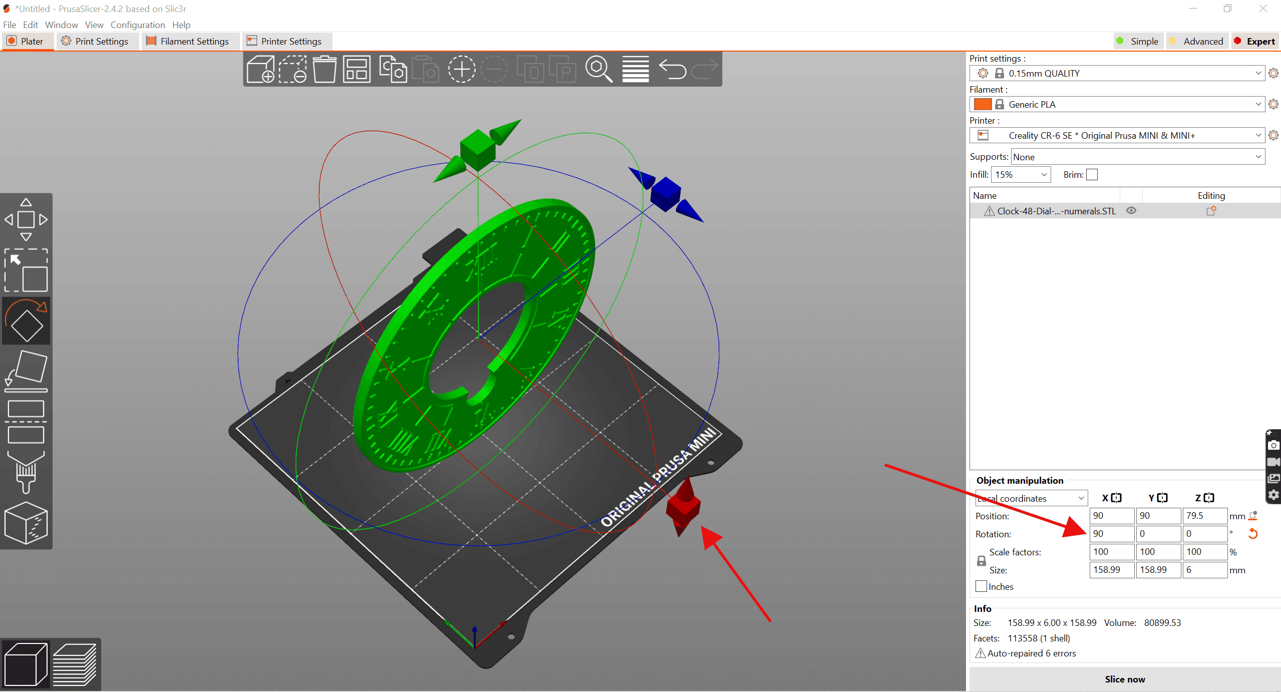
Normally when using a Slicer to split your part you will be splitting it at the surface of the bed, so we need to orientate the part so the split line is on the bed and to do this we need to rotate the part by 90 degrees. Click on the Rotate symbol indicated to open the screen shown above. To make sure you get the correct readings for position and rotation in the Box at the bottom right change the coordinates to Local.


Now grab the red handle and pull down, a box appears indicating the angular movement, keep pulling till it reaches 90 degrees, if it's difficult to get it exact slide the handle towards the centre and it will lock on 90. Alternatively, type in 90 degrees into the Rotation coordinates as shown.


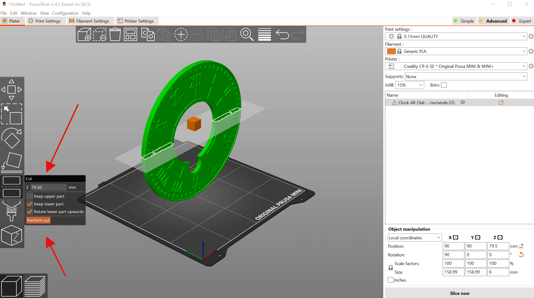
Now click on the Split or Cut symbol on the left to bring up the little Box and select the top option only now click on Cut. 


Now type in 270 degrees to lay the part back down on its back. That's the first half done so you can now go back to the Files menu and Export the file as a new STL file.


Now you have selected the bottom half of the dial to split and bring onto the top of the bed.  Now repeat the steps from before to lay it flat and then export the Bottom half of the dial.


Other methods

There are a lot of alternative slicers that can be used for this task, an internet search for 'split an STL file' will supply you with many alternatives. However, a better alternative may be 'Meshmixer' it has a fairly straightforward Splitting function they call Plane Cut but will also repair any damage to the model that has occurred as well. This latter function can be useful on its own if you get a model that is damaged.

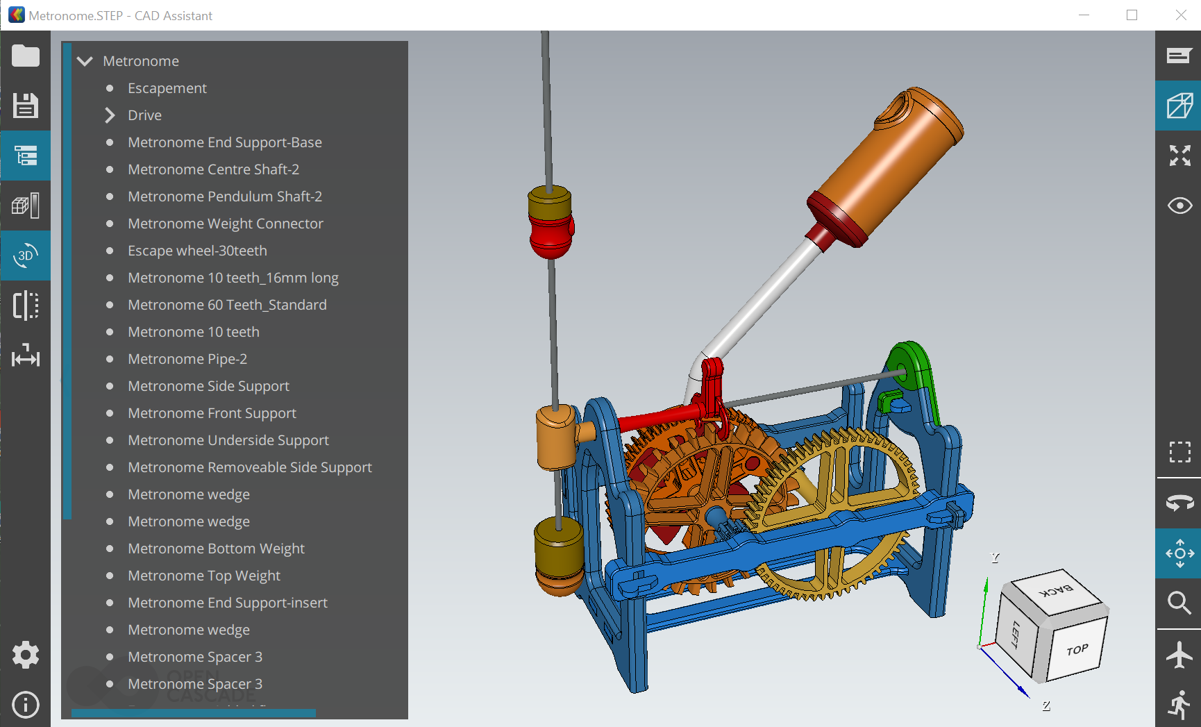
From a personal viewpoint I would always prefer to split parts in a CAD program I find it easier that way and in the main causing less damage to the part as it is always best to be using STP files for this task rather than using the STL files.


Thursday 30 June 2022

Excel files to help you design Gear Trains for wooden clocks


Spreadsheet to calculate the length of clock pendulums

If you have decided to design and build your own wooden clock then the following charts should give you some idea of how to tackle the tricky mathematical bits that are needed to make sure that the clock can run accurately throughout the day. Some of my earlier posts should have introduced you to some of these formulae that are used in this process. The idea here though is that we try to automate the process using Excel to do the heavy lifting and at the same time give you the opportunity to try out different combinations needed to me the constraints of the design you have in your head.

This first chart is used to calculate the length of the clock's pendulum which in turn uses various combinations of gears to achieve this, with you inputting tooth numbers into the appropriate box.

Basic concepts
  • Minute shaft makes 1 revolution every 3600 seconds

  • You are using a Graham Escapement that stops the rotation 2x for each completed swing(Tic Toc)

  • metric units

  • g= 9.8m/s/s

  • T= pendulum period of time for a Tick and A Tock

  • pi= 3.14159

  • length of pendulum = g(T/(2 *pi))2

  • If you aim to have a second hand then the Escapement wheel should rotate once in 60 secs.

The chart provides inputs for a maximum of 3-wheeled Gear Train and if you only use 2 then fill the appropriate boxes with the number 1, it also requires you to provide a pair of gears with a Wheel and a Pinion for each pairing. You must only input figures into the Green coloured boxes as the orange ones contain the Formulae to calculate the value.
If you want to add other combinations to the green area either clear an unwanted row or use the normal Excel technique to copy the whole Green and Orange bottom row of boxes and paste them to the row below.
Click on the picture below to download the Excel File.


Spreadsheet to calculate Gear tooth Profile.

I have always used a modified version of the standard gear tooth profile so as to give me more clearance between teeth and a bit more leeway when cutting the teeth by hand or on a scroll saw. The most important thing with regards to tooth profile is consistency in the pitching of the teeth. The charts below reflect this and the details are given for both the large gear and the Pinions in the most used tooth sizes.

Again if you want to add other combinations to the green area either clear an unwanted row or use the normal Excel technique to copy the whole Green and Orange bottom row of boxes and paste them to the row below.
Click on the picture below to download the Excel File.

PCD is the Number of TeethX Mod
Outside Diameter is (Number of teeth + 2)X Mod
Root Diameter PCD-(ModX3)


Spreadsheet to calculate centre distance between a Pair of Gears

This is probably the simplest of the charts as it simply calculates the distance between the two mating gears by adding the two Pitch Circle Diameters (Ø50 mm in this case) together and dividing by 2. If you experience difficulty with distortion of the gears that causes problems with assembly then you might want to increase this by 0.5 mm.


Tuesday 28 June 2022

Useful File types for wooden clocks builders - Step File

I have included STP or STEP files with most of the clocks that you can purchase as these files provide you with exact 3-D models of the clock that you can use in your 3D CAD program to modify any of the parts.

That is useful if you own and use 3D CAD software but if you don't then the files can be used in conjunction with an STP file viewer program to provide you with a great deal of extra information about the parts of the clock and the way that they fit together.

There is a considerable number of these available on the internet, some free and some not so much. I have only looked at the free ones as, to be honest, you should be able to get all you need from them. The programs fall into two groups, On-line where you upload the files you want to view and PC or mobile Android or iOS based.

What I was looking for in a viewer was first and foremost how easy and intuitive it was to use and manipulate the parts or assemblies when loaded. Secondly was whether it would produce a list of parts in an assembly and whether it would highlight a part within an assembly when clicked either in the model or the parts list. This is important as it is sometimes difficult to find parts and identify them when you click on either the part or the part in the list. 

Autodesk Viewer

Starting with the Online STP viewer my clear favourite here is the viewer from Autodesk, simply called the Autodesk Viewer which will open over 80 file types including STP,  STL and Solidworks, etc.


Once you have registered and signed in, use the Model Browser to find the part of the assembly you want to view. once loaded as shown below the assembly can be opened up in the Model browser where you can click on individual parts or groups to make them either visible or invisible. It would benefit you at this stage to either read the instructions or set up some of the settings, I advise you to do
this as it makes it easier, later on, to manipulate the model and interrogate it for more information on the parts.


Now you are ready to use the viewer, one of the rather nice things you can do with the loaded assembly is to explode so that the parts can be more easily identified, this is simple simply click on the Explode symbol at the bottom and then slid the blue ball to the right to see all the parts fly apart. 


To see individual parts without the clutter of the other parts around it simply click on the part in the parts list and the other parts disappear, to bring them back right-click on the same part and click on the Show all message to bring them back. finally, on this I would recommend you go into Configuration - Display settings and turn off 'Ghost hidden objects' as this makes the visible part more difficult to see clearly.


e


eDrawings

This next one can be downloaded to run on your PC or Mobile no Online option here. This is similar in many ways to the Autodesk Viewer but can load Solidworks files as well if you need that functionality. It is also slightly faster to load larger files as there is no internet connection needed.


Functionality on this one is pretty much the same as the Autodesk viewer with a Parts tree showing all the parts in their sub-assemblies with the same abilities to hide and show individual parts or sub-assemblies. Identification of those parts is easily done as highlighting in the parts tree also highlights the part on the model. 


Exploding of the assemblies is also similar to the Autodesk Viewer. Not much to choose between these first two and may come down to a preference for either PC or Online-based.

CADassistant

CAD assistant has similar functionality to the above and is either PC or mobile-based which may well be useful to iPad owners. It lacks the ability to explode assemblies but does have the functionality to change or add colour to a part which may well be the function that you are looking for.

I found it slightly more difficult to use than the others but to be fair that may be just me and certainly the ability to add colour could well make it worth looking at. If you click on the image below you should be able to download the STP files for this project.


So those are the ones that I consider worth using when you are trying to find more information about the wooden clock design you are going to build. Each has there merits and no reason for you not to try each one before you decide.